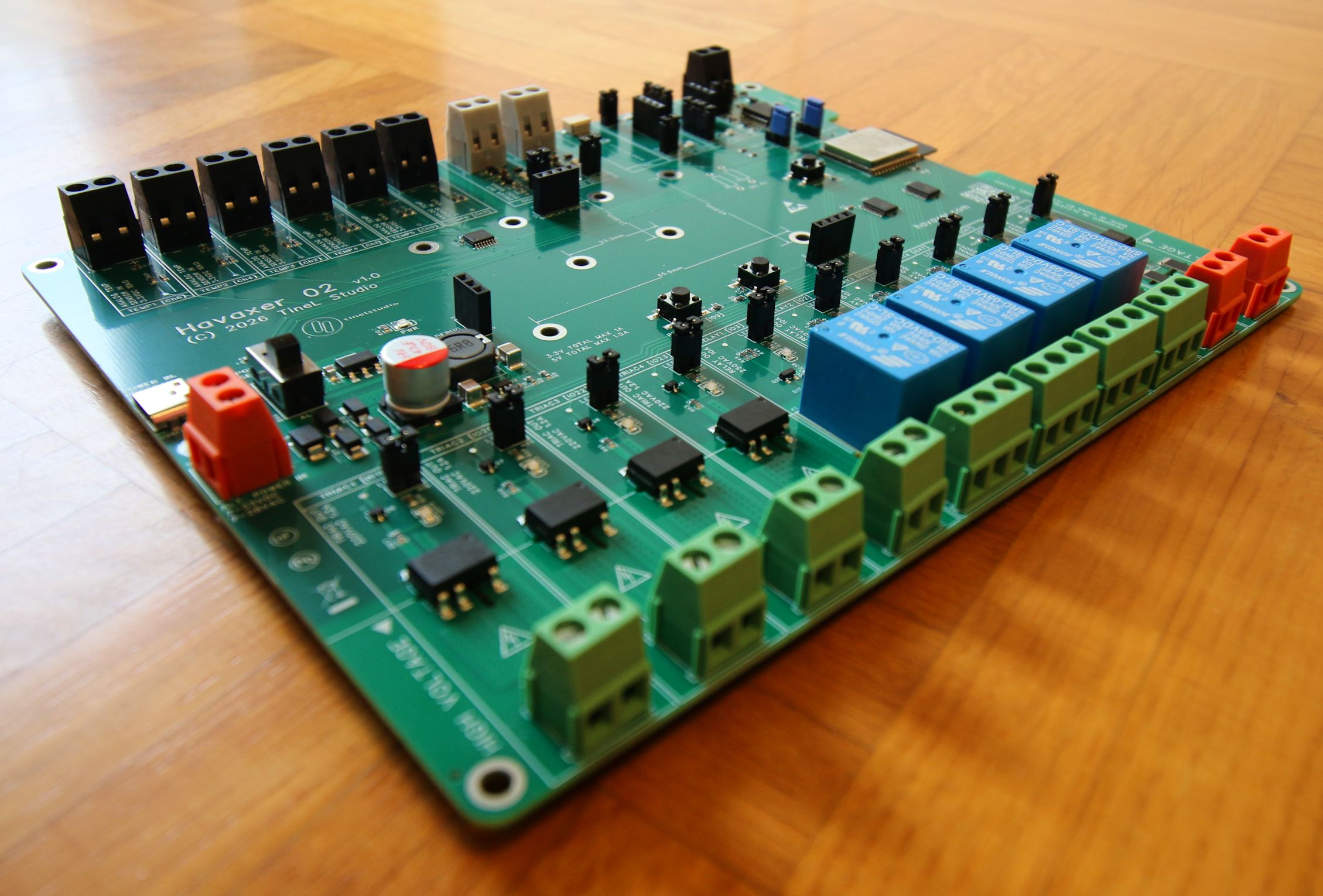
Havaxer™ 02 is the larger of the two boards: six temperature inputs, two mains inputs, four relays, four triacs and two signal outputs, around a soldered ESP32-C6.
That MCU makes it an IoT controller: Wi-Fi 6, Bluetooth 5 LE, Zigbee and Thread on board, and an example application that already speaks MQTT and Modbus.
02 can be optionally fitted with an OLED. It has two built-in buttons (+ reset), an eBUS adapter wired via a UART interface and an additional twin IO.
It was originally designed to control a complete HVAC system with two circuits, each able to heat or cool.
The MCU comes pre-programmed with my example application, for demonstration and testing only. Otherwise you write your own application and program the MCU yourself.
IoT and networking
The 02 is an IoT controller, not a relay board with a radio bolted on. The ESP32-C6 carries Wi-Fi 6, Bluetooth 5 LE, Zigbee and Thread on an on-board antenna, and the example application it ships with already runs MQTT and Modbus TCP. Give it an SSID and a broker address and the board starts publishing what its inputs read and accepting commands back.
That is enough to put an installation into Home Assistant, openHAB, Node-RED or any MQTT broker, with no gateway in between - which is the reason to choose the 02 over the 01 if anything has to leave the building.
What it publishes, how often, and what it accepts back is yours to write. The example is there to prove the path works, not to be your application - see Support.
Status
Dimensions, renders, photos and the full measurement reports are on the Versions page.
Specifications
Every capability below is explained on the Features page. The numbers here are what this model has.
The board is an industrial/consumer electronics manufactured PCB:
- FR-4, lead-free, green
- 4 layers, 1.6 mm thick
- 195 mm x 160 mm
- height approx. 20 mm
- weight approx. 209 g
- room temperature 0 to +40 °C
- all components are RoHS compliant
The MCU is the Espressif ESP32-C6-WROOM-1 N8 model and provides:
- 32-bit RISC-V architecture
- 1-core CPU with max 160 MHz
- 8 MB flash
- 2.4 GHz Wi-Fi 6 with an on-board PCB antenna
- Bluetooth 5 (LE)
- Zigbee & Thread
Connections:
- TIO header (twin general purpose input/output, 3.3 V)
- UART header (3.3 V)
- eBUS adapter to UART
- I2C display header (3.3 V)
- I2C QWIIC connector
- USB-C connector (programming, debugging and power)
- alternative power supply terminal (7-33 VDC, 7-22 VAC)
Inputs:
- 6x analog temperature sensor (NTC 10k)
- 2x mains optocoupler (250 VAC)
All inputs are multiplexed to one MCU pin, so only one programmatically selected input can be read at once.
Outputs:
- 4x mechanical relay (250 VAC, 10 A), one shared with TIO
- 4x solid state relay - triac (220 VAC, 1.2 A)
- 2x driver (5 VDC, 100 mA), one shared with TIO
All outputs are wired via additional hardware gates that need to be opened programmatically.
Supplied as a bare board. No enclosure is included.
Terminals
Every terminal carries its own name and rating on the silkscreen. Mains terminals are on the bottom edge, low voltage on the top edge - see Terminals and wiring.
| Terminal | Function | Rating | Connector |
|---|---|---|---|
T1 |
Alternative power in | 7-33 VDC, 7-22 VAC | orange, 2-pin |
T2 |
eBUS | per eBUS specification | black, 2-pin |
T3-T8 |
TEMP1-TEMP6 | 3.3 VDC, 10 kΩ NTC | black, 2-pin |
T9, T10 |
OC1, OC2 mains signal in | 250 VAC | orange, 2-pin |
T11-T14 |
RELAY1-RELAY4 | 250 VAC, 10 A | green, 3-pin |
T15-T18 |
TRIAC1-TRIAC4 | 220 VAC, 1.2 A | green, 2-pin |
T19, T20 |
SIG1, SIG2 | 5 VDC, 100 mA | grey, 2-pin |
Screw terminals are 5.0 mm pitch.
Headers and connectors
| Header | Function |
|---|---|
H1 |
Debug power, 3-pin |
H2 |
Buttons port, 4-pin |
H3 |
Display port, I2C, 4-pin |
H4 |
TIO selector, 3-pin: TIO-5 or SIG2 |
H5 |
TIO selector, 3-pin: TIO-4 or RELAY4 |
H6 |
EBUS ON, 2-pin |
H7, H8 |
UART transmit and receive: line to MCU + LED enable, 4-pin |
H9 |
UART port, 4-pin |
H10, H11 |
TIO LED enable, 2-pin |
H12 |
TIO port, 4-pin |
H13-H24 |
LED ON per input and output, 2-pin |
CN1 |
QWIIC, 4-pin 1.0 mm |
USB1 |
USB type-C |
SW1 |
Button, RESET |
SW2, SW3 |
Buttons, PBL/BOOT - left, PBR - right |
SW4 |
Power source selector, USB or alternative power in |
Headers are 2.54 mm pitch.
IO map
Printed in full on the board's bottom silkscreen, and matching the reference firmware exactly.
| IO | Function | IO | Function |
|---|---|---|---|
IO0 |
selected input, ADC | IO12 |
USB D− |
IO1 |
input selection bit 0 | IO13 |
USB D+ |
IO2 |
RELAY2 | IO14 |
N/A, not brought out by the ESP32-C6-WROOM-1 |
IO3 |
RELAY1 | IO15 |
outputs off/on switch |
IO4 |
TIO-4 or RELAY4 | IO16 |
TXD0, UART TX |
IO5 |
TIO-5 or SIG2 | IO17 |
RXD0, UART RX |
IO6 |
I2C SDA | IO18 |
SIG1 |
IO7 |
I2C SCL | IO19 |
TRIAC1 |
IO8 |
PBR | IO20 |
TRIAC2 |
IO9 |
PBL/BOOT | IO21 |
RELAY3 |
IO10 |
input selection bit 1 | IO22 |
TRIAC3 |
IO11 |
input selection bit 2 | IO23 |
TRIAC4 |
The multiplexer channel order is deliberately not sequential:
| Channel | Ch0 |
Ch1 |
Ch2 |
Ch3 |
Ch4 |
Ch5 |
Ch6 |
Ch7 |
|---|---|---|---|---|---|---|---|---|
| Input | TEMP5 | TEMP4 | TEMP3 | TEMP6 | TEMP2 | OC2 | TEMP1 | OC1 |
Power
Brought via USB-C or alternative power supply terminal.
| 5 V rail, total | 1.5 A |
| 3.3 V rail, total | 1 A |
| Consumption, worst case | ≈ 2.5 W - see Versions |
Some headers provide power rails.
Key components
What is switching your mains, and what the isolation is.
| Function | Part | Manufacturer |
|---|---|---|
| MCU | ESP32-C6-WROOM-1-N8, 8 MB | Espressifopen_in_new |
| Mechanical relay | SRD-05VDC-SL-Copen_in_new, 10 A | Songleopen_in_new |
| Solid state relay | BC3213Aopen_in_new, zero-cross opto-triac | BC |
| Mains input optocoupler | SFH6286-3Topen_in_new, AC input | Vishayopen_in_new |
| eBUS isolator | CA-IS3621LWopen_in_new, reinforced, integrated isolated DC-DC | Chipanalogopen_in_new |
| Input multiplexer | 74HC4051PWopen_in_new | Nexperiaopen_in_new |
| Output buffers | SN74LVC244Aopen_in_new | Texas Instrumentsopen_in_new |
| Buck converter, 5 V | LMR51430XDDCRopen_in_new, 3 A, 4.5-36 V | Texas Instrumentsopen_in_new |
| 3.3 V regulator | TLV1117LV33open_in_new, 1 A | Texas Instrumentsopen_in_new |
| Resettable fuse | 0603L010/24XRopen_in_new, 100 mA hold, 300 mA trip | LUTE |
Known Limitations
Versions 1.0
-
Using the UART port standalone (no eBUS) has a known limitation. The RX line is known to leak a tiny amount of current - enough to cause signal noise. To prevent this, simply wire the right pin of the
EBUS ONheader (H6) to the board's ground.
Issue #14open_in_new -
The alternative power supply's printed range
7-33VDC / 7-28VACis over-declared at the AC end. Should read7-33VDC / 7-22VAC. On AC it is the peak that counts, and a 22 V RMS supply already peaks at 31 V.
Issue #16open_in_new
What is not included
- no enclosure - the board is supplied bare
- no display, unless an optional OLED is ordered
- no temperature sensors, unless ordered
- no power supply and no USB cable, unless the optional cable is ordered
- no I2C pull-up resistors - positions are provided, deliberately unfitted, see I2C
- no schematic - the PCB layout PDF is published, the schematic is not
- no CE, FCC or UL marking
- no firmware support; the example application is for demonstration and testing
Installation and safety
This board switches mains. Read Installation and safety before wiring it.
Pricing, Order
Before shipping, each board is inspected, programmed and tested. If optional items are ordered, they are also inspected, tested and attached to the board.
| Item | Price | Availability |
|---|---|---|
| Havaxer 02 | € 169.90 | In stock, now |
| OLED 0.96", optional | € 4.99 | In stock, now |
| OLED 2.42", optional | € 26.99 | Out of stock, approx. 1 week |
| Temperature sensor, 5 m, optional | € 15.99 | Out of stock, approx. 1 week |
| USB A-C cable, 2 m, optional | € 5.99 | Out of stock, approx. 1 week |
| Shipping, inside EU only | € 15.99 | 1-2 working days |
Sold by a private individual, not a registered business. Import VAT and duty are already paid and included in the price - no VAT is charged on the sale, and no VAT invoice can be issued. Business buyers cannot deduct VAT on this purchase.
Shipping inside EU only.
Order it now by writing an email to order@havaxer.com or message on Telegram @havaxerinfo. More info.
Examples
This theoretical example shows what the Havaxer 02 was designed for: to control a complete HVAC system with two circuits, each able to heat or cool.